|
JESSE ENGINEERING CO.
1840 Marine View Drive, Tacoma WA 98422 Phone: (253) 922-7433 Fax: (253) 922-2536 |
|
|||||||||||||
|
|
||||||||||||||
|
Single Axis Benders | Power Carriage Benders | CNC Benders | Pipe Bender Tooling | Overhead Clamps | Pipe Shop Software Pipe Cutting Machines | Pipe / Flange Welding Machines | Used Pipe Benders | Past Projects | Parts & Service |
||||||||||||||
|
Pipe Shop Software |
||||||||||||||
|
|
To provide management and data flow within a pipe shop, from an upstream CAD system, and to our various pipe fabrication machines, Jesse Engineering has developed Pipe Shop II software. The Pipe Shop Software runs on an IBM-compatible PC computer in a Windows environment.It is designed to be used by a Pipe Shop Manager or Industrial Engineer. Pipe spool requirements can be downloaded from elsewhere for sorting and scheduling within the Pipe Shop. |
|||||||||||||
|
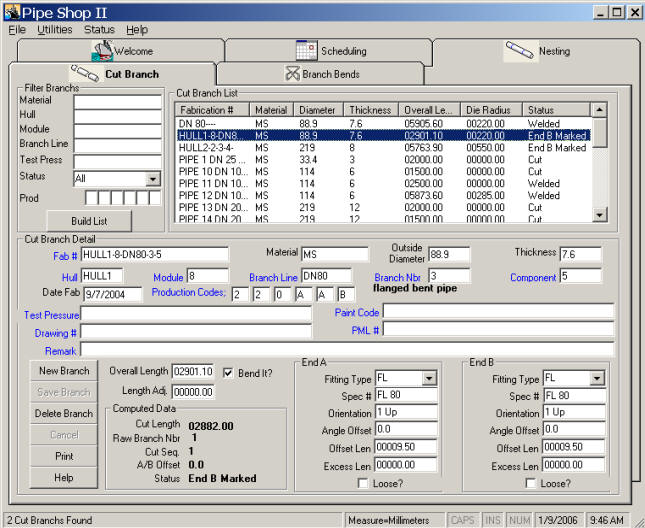
The office PC computer is the main point of data entry, manipulation, checking, and scheduling. Data is entered by keyboard, floppy disk, or through the data communication port. Data is sent to various machines on the pipe shop floor by direct data communication, floppy disks, or by print out. Important features of the system include: Data Entered Once - The Software develops required pipe cut lengths, flange offset angles, optimized and nested cut schedule, pipe spool routing, and individual machine instructions keyed to Pipe Number. (See Figure 2) Flange Orientation - The system supports the bending of pipes with the flanges already welded in place. The system computes flange hole offset angles and adjusted cut lengths so the resulting spool pieces will fit correctly on the ship or other final application. |
||||||||||||||
|
|
||||||||||||||
| Figure 2 | ||||||||||||||
|
Machine Instructions Generated - The program provides each machine the correct data to process the particular spool piece identified by Pipe Number. The basic spool piece input is XYZ projections using the shipboard coordinate system. Spring back, radial growth, and stretch are corrections that are made for bent spools. Automatic Branch Pipe Generation - The program tags and sorts branch pipes (pipes with flanges on one end and saddle cuts on the other). These pipes are automatically arranged end to end to form single cut pipes. These special pipes are then cut on the Saddle and Hole Cutter to form two required branch pipes. Schedule and Material Optimization - The program automatically develops a suggested schedule that the operator can accept or modify. A cut schedule is generated for the saw line controller which nests the scheduled cut pipes onto the stock pipe to be cut in order to minimize waste. Data Storage and Retrieval - The software uses the widely accepted Microsoft FoxPro database program. Thousands of pipe spools can be stored in the database by Pipe Number. The data can be easily accessed for management analysis using FoxPro. The software includes an archiving feature that places completed pipe spools onto a floppy disk for later use. |
||||||||||||||
|
Figure 3 |
||||||||||||||
|
Specific operations within the system are discussed below. Design Data - This data is entered for each pipe spool to be processed. The data can be entered from the keyboard or from another computer. Pipe spools are tracked by Pipe Number, Material, OD, Thickness, and Bend Radius (if required). Pipe spool descriptions are entered as lengths projected onto the XYZ coordinates of the ship. Flanges, if required, are entered by their specification number and final orientation on the ship (1 or 2 holes up). Scheduling data includes required date of the spool, its routing through the line, and the bender it should be bent on. The software has default values for much of the input data making entry of this type of data optional. System Data - This data is entered once at the keyboard and is subsequently used by the software to compute data for each pipe spool based on the Design Data input. (See Figure 4) Pipe Data uses Material, OD, Thickness, and Bend Radius as key indices for looking up spring back factors, etc. System Data uses Material, OD, and Thickness as key indices to lookup saw kerf, bender settings, etc. Flange Data uses Material, OD and Flange Specification Number as key indices for looking up the number of flange holes, welding set back dimension, welding parameters, flange marking machine pattern number, etc. |
||||||||||||||
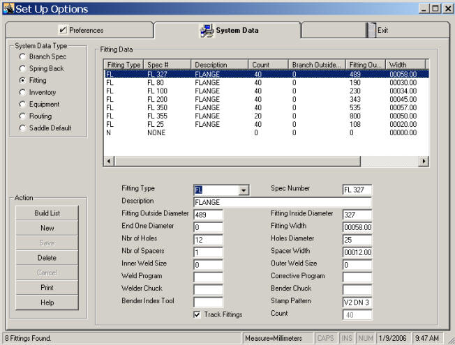 Figure 4 |
||||||||||||||
|
Office PC Computer - The computer, using the Pipe Shop Software, converts the input data to specific machine instructions keyed to Pipe Number. The program modules used are: XYZ Conversion - The pipe spools are entered as projected lengths on the XYZ coordinate system of the ship. These are converted to the standard pipe bender coordinates of Bend Angle, Tangent Length, and Rotation Angle. The expected overall pipe length is also computed. Adjustments - The pipe bender instructions are corrected for spring back, and radial growth. The cut length is computed considering radial growth, stretch, and flange set- back factors. Flange Orientation - Two flange orientation angles are computed using the XYZ input data. (See Figure 5) The flange hole offset angle is the angle the flanges are offset from each other when they are welded to the straight pipe. The computation of this angle considers the angle changes caused by the bending process, final flange hole orientation angles, and the number of holes in each flange. The initial bender rotation angle is automatically set by the bender before the first bend is made. This places the flange holes of the spool to the correct orientation aboard the ship. The bender chuck indexes the flange to 1 hole up before it sets the initial rotation. |
||||||||||||||
 |
||||||||||||||
|
Figure 5 |
||||||||||||||
|
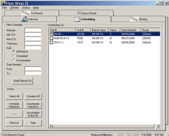
Schedule, Optimization and Nesting - The software presents the operator with all the entered pipe spools sorted by Material, OD, Thickness, Bend Radius, and Required Date. A “Y” is automatically placed by each spool with a required date sooner than a selected date. This becomes the suggested schedule. The operator can manipulate the schedule by various sorting routines and can change the “Y” designation. The schedule set by the operator is automatically scheduled by the software and sent to the various machines and printer. The cut pipes are optimized at the saw line against the measured stock pipe lengths. Reverse Bends - The operator can instruct the software to reverse the bend of any selected pipe spool. This is useful if the original configuration has a bender interference problem. The software reverses the XYZ entry data and recalculates the related data. Reverse bends are flagged in the database. Data Management - The data is held in database files. These can be copied and analyzed as desired outside of the software package. The software will archive (write) completed pipe spool data (as designated by a status code) to a floppy disk. This removes the data from the database. Pipe Cutting - The pipe cutter control computer receives the scheduled pipe spool data by Pipe Number, Material, OD, Thickness, Required Date, Cut Length and Routing Data. Pipe spools are then automatically nested, marked, cut and routed in accordance with the schedule. The cut order, pipe number, and flange offset angle are sent to the flange welder as the spools are cut. Flange Marking - The Flange Marker computer receives the Pipe Number and Mark Pattern and stores it in a data base format. The operator highlights the pipe number desired and the marker automatically marks that pipe number on the edge of the flange in accordance with a pre selected pattern. The Pipe OD, Required Date, and Flange Data are also received and displayed so the operator can identify the type of flange to be marked and do so in an orderly manner. Flange Welding - The Flange Welding station operator receives a printout showing the Pipe Number, Cut Pipe Length, Flange Offset Angle, and flange welding parameters. The machine settings associated with the pipe number are used to set up and operate the machine. The pipe number of the pipe being processed and the required offset angle are displayed as sent from the saw line controller. The proper flanges to be mounted should be available with the pipe number already engraved on them. The Flange Welder Console has a bar code reading wand attached that can be used to automatically verify the number of the pipe being welded. CNC Pipe Bending - Scheduled bent pipe spool data is sent to the bender and stored. The Wallace Coast CNC II Controller holds 1000s of pipe spools configurations by pipe number. All data needed to automatically bend the pipe is stored and displayed. The operator can change data or create a new bend configuration at the console. The operator observes the pipe number to be bent and scrolls to that number on the console display. Alternatively, the operator may use the bar code reading wand attached to the console to read the pipe number. The operator loads the pipe and the bender automatically make the required 3-D bend configuration with proper flange hole orientation. The operator can also choose to make the bend manually or semi-automatically. The pipe spool status is automatically changed to “C” when the bend is completed. The pipe spool data can be uploaded to the office computer where its status or configuration change is automatically updated in the main database. Pipe Spool Completion – A portable bar code reader can be provided that is compatible with the Office PC Computer. Completed pipe spools are read by the reader and the numbers uploaded to the Office PC Computer. The completed status is then automatically recorded. |
||||||||||||||
|
|
||||||||||||||
|
Jesse Engineering offers Pipe Shop II networked to our machines for a complete CAD/CAM environment, with modifications and enhancements to suit each project. |
||||||||||||||
| Printer friendly version | ||||||||||||||
.jpg)

.jpg)